We once watched a compact 12V battery enclosure swell like a balloon after a minor overcharge, a stark reminder that ventilation and cooling aren’t optional. In solar storage, the safest path starts with chemistry choice, system sizing to avoid thermal runaway, and a layout that promotes continuous airflow. We’ll outline how to couple BMS feedback with active cooling, ensure proper enclosure ratings, and establish disciplined installation and maintenance practices so you’re prepared for faults and environmental stress—and you’ll see why these steps must come first.
Key Takeaways
- Enclosure design with adequate ventilation, clearances, rated materials, and fault-tolerant venting to manage heat and gas safely.
- Safe installation practices: verified components, compliant wiring, proper torque, fault interlocks, and accessible maintenance routes.
- Robust BMS-driven monitoring: SOC, voltage, current, temperatures, tamper-evident logs, and validated fault responses during commissioning.
- Thermal management strategy: active cooling as needed, sensors integrated with alarms, airflow planning, and margins to prevent hotspots.
- Emergency and maintenance protocols: documented isolation steps, incident logging, routine inspections, and safe fault recovery procedures.
Choose the Right Lithium Chemistry for Solar Storage
Choosing the right lithium chemistry for solar storage hinges on balancing energy density, cycle life, safety, and cost. We assess chemistry tradeoffs by evaluating both performance metrics and failure modes under real-world conditions, including temperature fluctuations and partial state-of-charge cycling. Lithium iron phosphate offers enhanced long term safety and thermal stability, with lower energy density but robust cycle life and lower risk of thermal runaway. NMC chemistries provide higher energy density but impose stricter thermal management and safety controls. Lithium titanate delivers fast charge/discharge and strong cycle life yet at higher cost and lower energy density. We favor configurations that meet our reliability targets, incorporate robust BMS protections, and minimize material risks. Ultimately, selection aligns with system tolerance for risk, cost constraints, and long term safety goals.
Size the System to Prevent Overuse and Thermal Risk
We size the system to stay within safe current and thermal limits, reducing overuse risk and heat buildup. By defining clear System Size Limits and planning for worst‑case scenarios, we mitigate thermal risk and maintain performance. We’ll review typical overuse scenarios to ensure the design remains within safe operating margins.
System Size Limits
How large a solar-plus-Lithium system should we allow before risking overuse and thermal stress? We, the system designers, set clear limits to protect safety and longevity. Our approach is data-driven: define usable energy, peak loads, and margin for thermal response. We implement conservative thresholds and continuous monitoring to enforce them, integrating system sizing decisions with real-time feedback. We avoid oversized configurations that force excessive cycling or hidden heat buildup.
- Establish maximum continuous discharge/charge rates based on cell chemistry and cooling capacity.
- Specify allowable storage capacity per inverter rating to maintain safe operating temperatures.
- Define automatic shutoffs tied to thermal monitoring when temperatures exceed thresholds.
- Document each configuration with safety margins and maintenance intervals to preserve performance.
Thermal Risk Mitigation
Thermal risk mitigation begins with sizing and controls that keep battery temperatures within safe, predictable bounds, preventing overuse and heat buildup. We design the system to limit current draw, balance charge cycles, and match cell chemistry to anticipated solar profiles. Our approach integrates thermal sensors, active cooling options, and conservative state-of-charge targets to maintain safe operating temperatures under all reasonable conditions. We quantify heat generation, implement margin-based alerts, and enforce automatic shutdown if temperatures approach limits. We assess enclosure ventilation, isolation of cells, and enclosure materials to reduce heat transfer paths. By prioritizing thermal runaway prevention, we minimize heat accumulation and venting risks, preserving integrity and safety margins. Continuous monitoring, fail-safe interlocks, and clearly defined response actions complete the mitigation strategy.
Prevent Overuse Scenarios
To prevent overuse and thermal risk, we size the system to limit peak and cumulative current draw, matching battery capacity to expected solar profiles and load demands. We ensure wiring, breakers, and BMS settings reflect anticipated currents to avoid stressing cells. We address overcharging myths by enforcing charge termination, proper monitoring, and robust fault handling. We acknowledge thermal runaway risks and design for adequate cooling, isolation, and alerting if temperatures rise beyond safe thresholds.
- Size for peak and average loads to keep current within safe margins
- Align battery capacity with solar generation and usage patterns
- Implement strict charge termination and real-time temperature monitoring
- Include clear fault protocols and automated safety actions to prevent misuse
Plan Layout and Airflow After Choosing Chemistry
We must plan layout and airflow after selecting chemistry to ensure safe operation and effective cooling. We’ll address space requirements, access for maintenance, and containment paths for any thermal events, aligning with chosen cell chemistry. This discussion sets the framework for optimized ventilation, clearance, and enclosure design that mitigates fire and gas risks.
Plan Layout Considerations
How should we arrange the plan layout and airflow after selecting a chemistry? We design layouts that minimize heat buildup, enable rapid detection, and maintain access for maintenance and emergency response. Our approach balances enclosure volume, venting pathways, and separation from heat sources, with attention to space for thermal management devices and instrumentation. We align wiring, battery modules, and HVAC connections to reduce obstruction and improve air distribution while preserving fault isolation. We also document safety acronyms and chemistry considerations to ensure consistent communications across teams. Clear zoning, cable routing, and clearance margins support safe operation and code compliance.
- Define enclosure zoning and pathway routes for efficient airflow and service access.
- Position vents, intakes, and exhausts to prevent recirculation.
- Allocate space for thermal management, sensors, and safety shutoffs.
- Standardize labeling, procedures, and safety acronyms for rapid response.
Airflow Post-Selection Chemistry
What happens to airflow once the chemistry is chosen? After selecting a chemistry, we map airflow needs to the enclosure layout, ensuring that vent paths, clearance, and intake/exhaust pressures align with safety thresholds. Airflow considerations focus on avoiding stagnation, hot spots, and gas buildup during normal operation and fault scenarios. We align fans, dampers, and baffles to maintain positive pressure where required and to protect sensitive components from cross-draft contamination. We also size filtration and vent routing to manage thermal margins and moisture control. Post selection chemistry drives the ventilation strategy, including transient responses to thermal runaway indicators. We document airflow targets, monitoring points, and procedural actions, so the system remains within design limits and maintains safe operating temperatures at all times.
Charging, Discharging, and BMS: Best Practices
Excellent charging, discharging, and BMS management are essential for safety and longevity in solar lithium systems. We implement strict procedures to ensure reliable operation and prevent hazards. Our approach emphasizes defined charging safety protocols, accurate state-of-charge tracking, and robust fault handling within the BMS. We avoid aggressive charging profiles that exceed cell ratings and we enforce conservative discharging limits to maintain voltage headroom and cycle life. Regular verification of sensor integrity and communications ensures timely anomaly detection. Proper settings reduce thermal stress and misbalance risks. All practices align with manufacturer guidelines and safety standards, with documentation for audits and maintenance.
- Set conservative charging safety limits and monitor SOC, voltage, and current continuously
- Enforce discharging limits to preserve cell balance and capacity
- Maintain accurate, tamper-evident BMS logs and alarms
- Validate firmware and fault response during commissioning and routine checks
Cooling and Enclosure Requirements for Lithium Packs
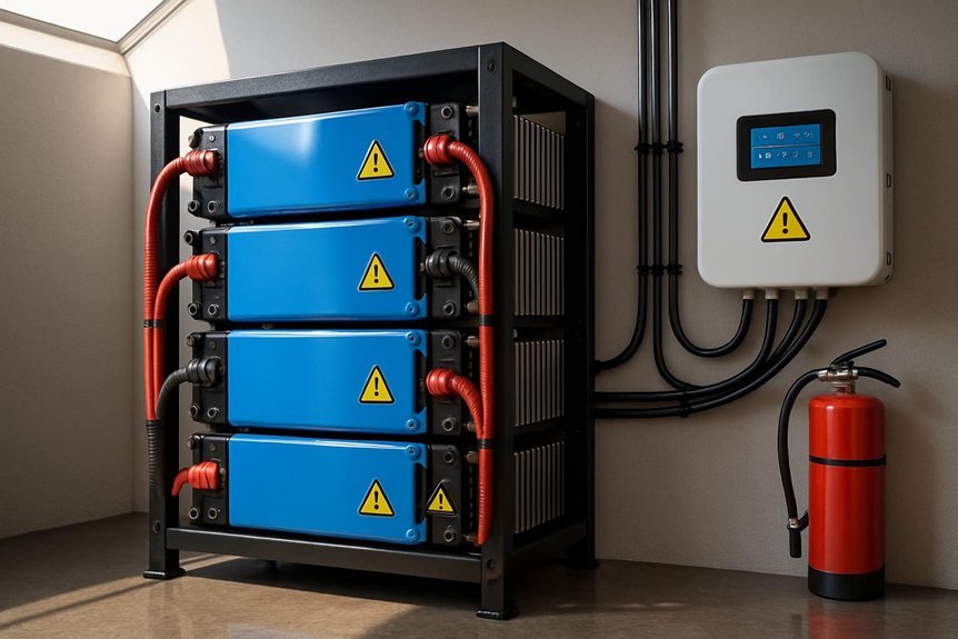
Cooling and enclosure requirements for lithium packs follow from safe charging, discharging, and BMS management. We approach enclosure design with rigidity and ventilation that prevent hot spots and thermal runaway risk. Our guidance prioritizes consistent airflow around modules, minimum clearance, and enclosure materials rated for battery temperatures. We specify active cooling when ambient conditions or pack density exceed thresholds, with monitored feedback from temperature sensors integrated into the BMS. We require robust seals to resist dust ingress while permitting venting in fault conditions. Enclosures must isolate cells from mechanical damage, chemical exposure, and moisture, using corrosion-resistant fasteners and strain relief for cabling. Considerations include enclosure placement, ingress protection, and ease of servicing while maintaining cooling requirements and safe operation.
Safe Installation and Wiring for Solar Storage
How do we guarantee safe installation and wiring for solar storage systems? We approach this with strict protocols, verified components, and documented procedures that minimize risk and maximize system reliability. Our focus is on containment, fault tolerance, and clear accessibility for maintenance, without compromising performance. We ensure compliant wiring routes, appropriate protection, and proper labeling throughout the run. Safety interlocks, correct torque on connections, and thermal management are integral to the process. We explicitly address solar insulation needs and mounting hardware compatibility to prevent overheating and mechanical failure.
- Verify component ratings and labeling before installation.
- Route cables with approved insulation and protective enclosures.
- Secure devices using suitable mounting hardware and torque specs.
- Documented commissioning, testing, and safety sign-off complete the loop.
Maintenance, Inspection, and Fault Response
Maintenance, inspection, and fault response are integral to sustaining safe, reliable solar storage systems. We implement a structured maintenance program that prioritizes component health, conductor integrity, and enclosure cleanliness. Our routine includes a defined schedule for electrolyte, cell impedance, and thermal monitoring, plus visual inspections for corrosion or physical damage. A documented maintenance check records voltages, temperatures, and state of charge limits to detect drift or degradation early. We emphasize consistent torque, cable routing, and venting checks to prevent arcing and thermal buildup. For fault response, we outline immediate isolation procedures, fault signaling, and system reconfiguration to maintain critical loads while diagnostics run. We train operators to recognize abnormal readings and report deviations promptly, ensuring containment without compromising safety or performance.
Emergency Procedures and Incident Recovery
In an emergency, we act quickly and deliberately to protect people and property while preserving system integrity. When an incident occurs, our team follows established protocols to minimize harm and restore capability without compromising safety. We document conditions, isolate affected modules, and coordinate with responders to prevent propagation. Our incident recovery focuses on assessing damage, replacing compromised cells, and validating thermal management and insulation before re-energizing. Clear communication and traceable steps ensure accountability and rapid return to service.
1) Activate emergency procedures and notify the safety officer immediately.
2) Isolate the faulted bay, disconnect power, and block access to utilizable paths.
3) Assess for thermal anomalies, leakage, or swelling; document findings.
4) Verify system integrity, perform functional tests, and restore safe operation.
Frequently Asked Questions
How Do Lithium Chemistries Affect Long-Term Degradation in Solar Apps?
We explain how lithium chemistry affects long term performance: degradation mechanisms in solar systems arise from SOC swings, temperature, and cycle life, influencing capacity fade and safety margins, so we monitor electrolyte stability and thermal management to sustain reliability.
What Are Typical Failure Modes in Confined Lithium Battery Enclosures?
We see the typical failure modes in confined lithium battery enclosures include thermal runaway, gas buildup, venting failures, fire, and structural breach; unrelated topic risks and spare parts shortages amplify safety concerns and response planning.
Can I Retrofit a BMS for Mixed Chemistries in One System?
We can’t safely retrofit a single BMS for mixed chemistries in one system. BMS compatibility varies by chemistry; mixed chemistry safety requires segregated management and validated interfaces to prevent cross-chemistry faults and thermal/charging conflicts.
How Often Should Thermal Imaging Be Performed on Solar Storage Packs?
We recommend a frequent cadence: we perform thermal imaging during monthly inspections and after any fault event. We align with defined frequency audits, track thermal windows, and document trends to maintain safety and reliability.
What Are Cost-Effective Non-Routine Failure Mitigation Strategies?
We implement cost-effective non-routine failure mitigation strategies by validating with short circuit testing and strict venting safety checks, documenting root causes, and updating procedures; we train operators to recognize anomalies and respond promptly to prevent cascading failures.
Conclusion
We’ve built a safety framework that’s as airtight as a pressure vessel. Stick to the chosen chemistry, size the system to avoid thermal runaway, and maintain strict airflow and enclosure standards. Our BMS-integrated monitoring, interlocks, and regular maintenance act as the valves and gauges of a well-tuned engine. In fault or heat stress, isolate quickly, preserve critical loads, and follow emergency procedures. With disciplined wiring, clear labeling, and routine checks, safety stays the constant current.

